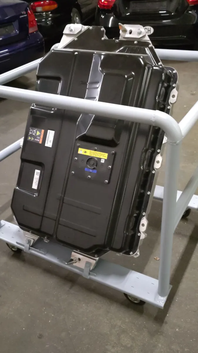
This will be an article on the complete disassembly of a Renault/LG Chem Traction Battery which will be used to power the Renault Twingo. Although this type of battery has been around since about 2013, there is not much information around on these units, although they are very well designed in my eyes.
This particular battery is from a 2020 Renault Master, the very same battery can also be found on the second series Renault Kangoo. It has a capacity of 36kWh, 33kWh usable. The battery is very similar to the one used in the widely popular first series Renault Zoe, just a few minor differences to be noted.
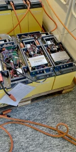
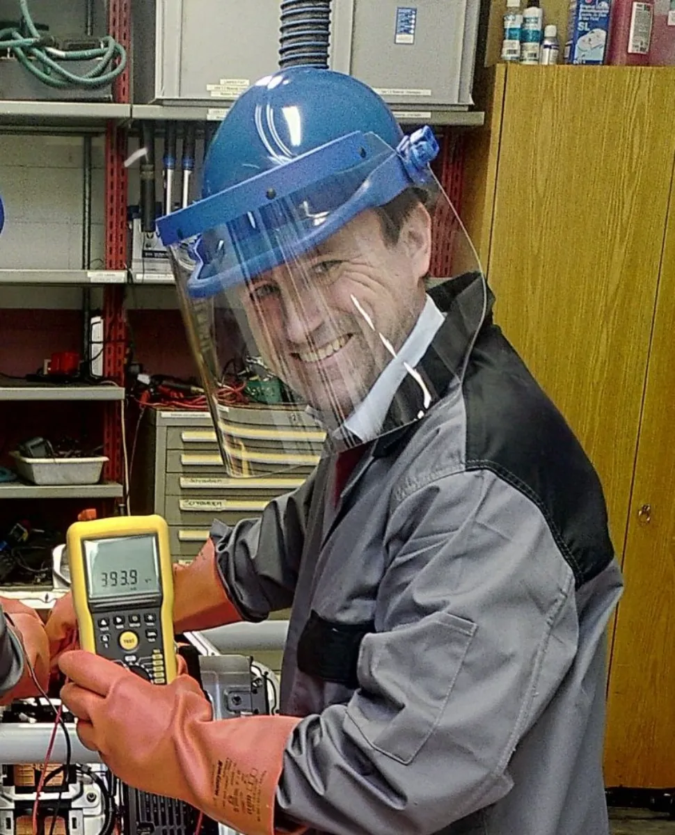
For all that follows now: Electricity kills! Please be sure to wear full PPE if you are doing similar things in your garage. I am wearing cotton long sleeve clothes, safety/ESD shoes, 1000V electrical safety gloves, helmet and visor in case of electric arc. Here, I am measuring the total voltage of the battery pack.
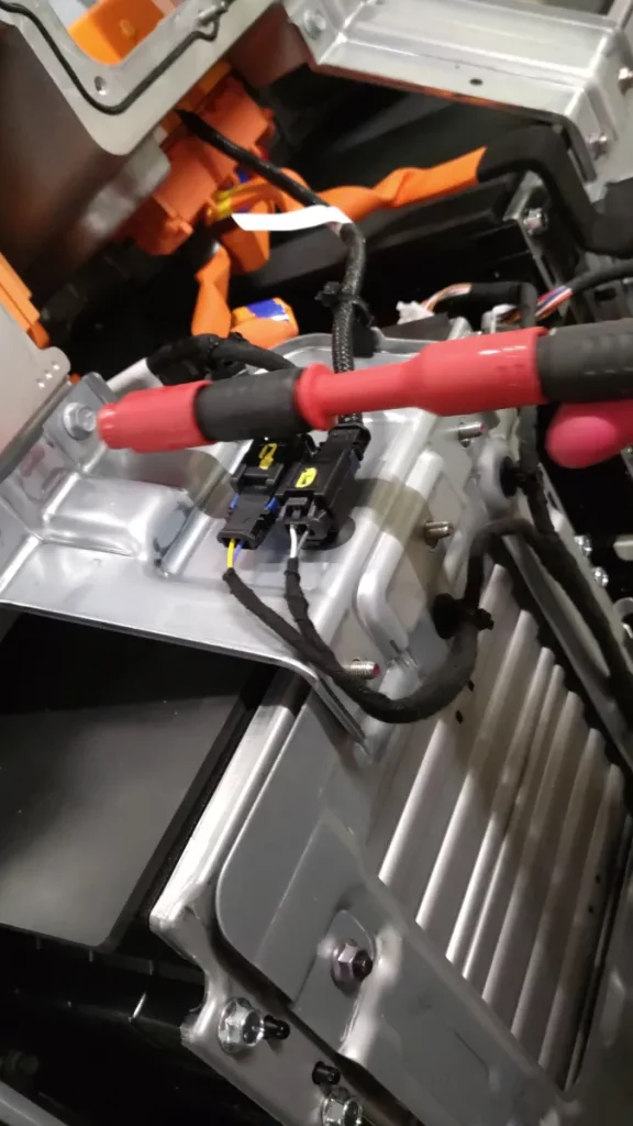
After removing the main cover of the battery, we first see the high voltage connections. The main connection to the car on the right side, the service disconnect on the left side.
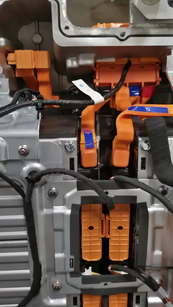
These here (the two black lines with a connector in the middle of the picture) are the pilot lines, one for the service disconnect and one for the main connector. The pilot lines are monitoring if the connectors are closed and disarm the connectors (by opening the main contactor) in case the connectors are getting opened on a live battery.
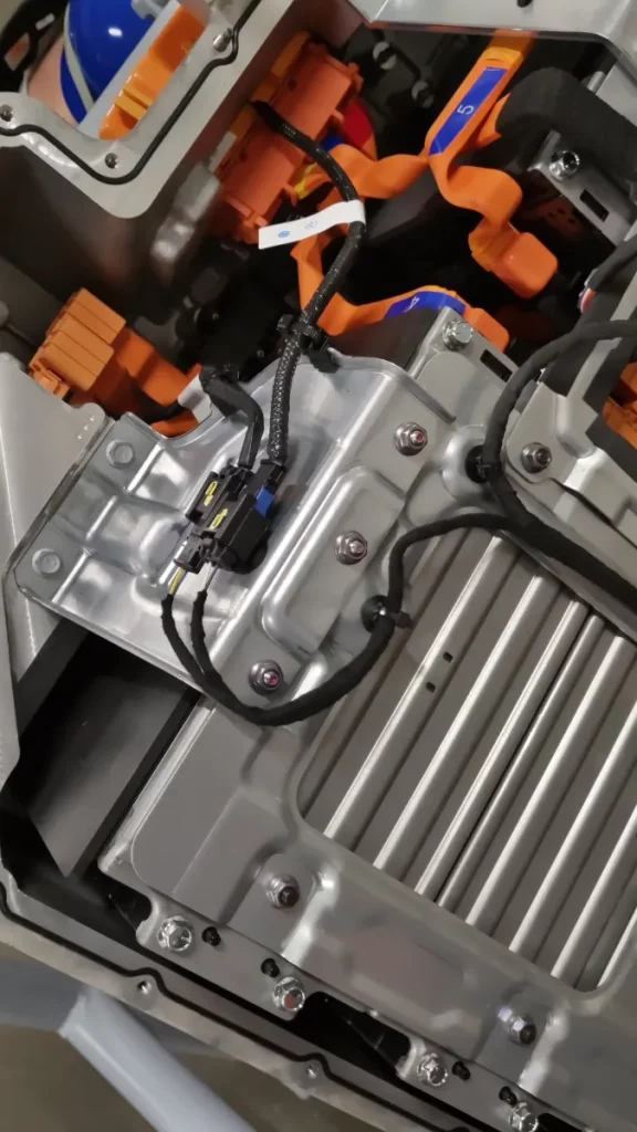
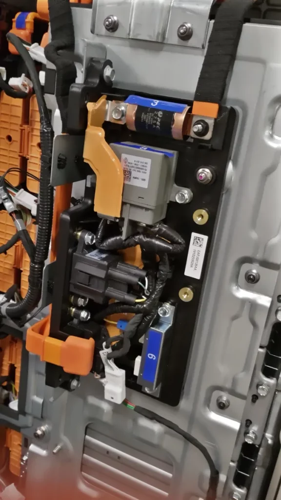
Within the battery box, sitting right on top of the battery modules, we find a module with the precharge circuit:
Let’s have a look inside this component!
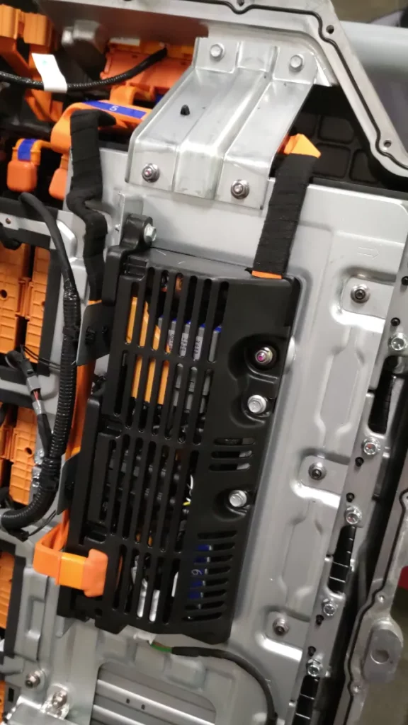
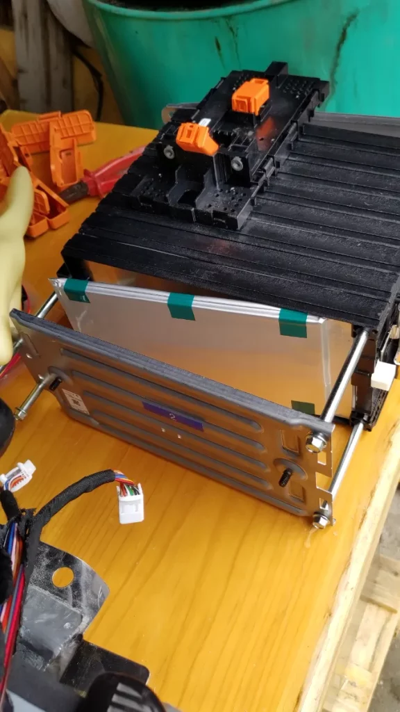
If we open the protection, it gets more visible: The main 275A fuse on the battery side on top, the main contactor (grey) just below, the black precharge relay further down and the precharge resistor (marked with a number 9) and the current sensor below the orange cable connection on the bottom left side.
Here we can see the BMS computer, which includes the voltage sensing boards and the BMS system in one enclosure, similar to e.g. the Orion BMS. The battery itself consists of 12 modules with 8 cells (technically 16 cells but in a 2p8s configuration), so we have 96 wires only for the voltage sensing cables, plus additional temperature sensors and other signalling cables.
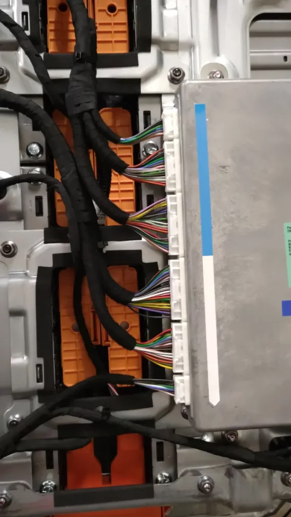
The wiring loom leads from the battery modules to the BMS computer.
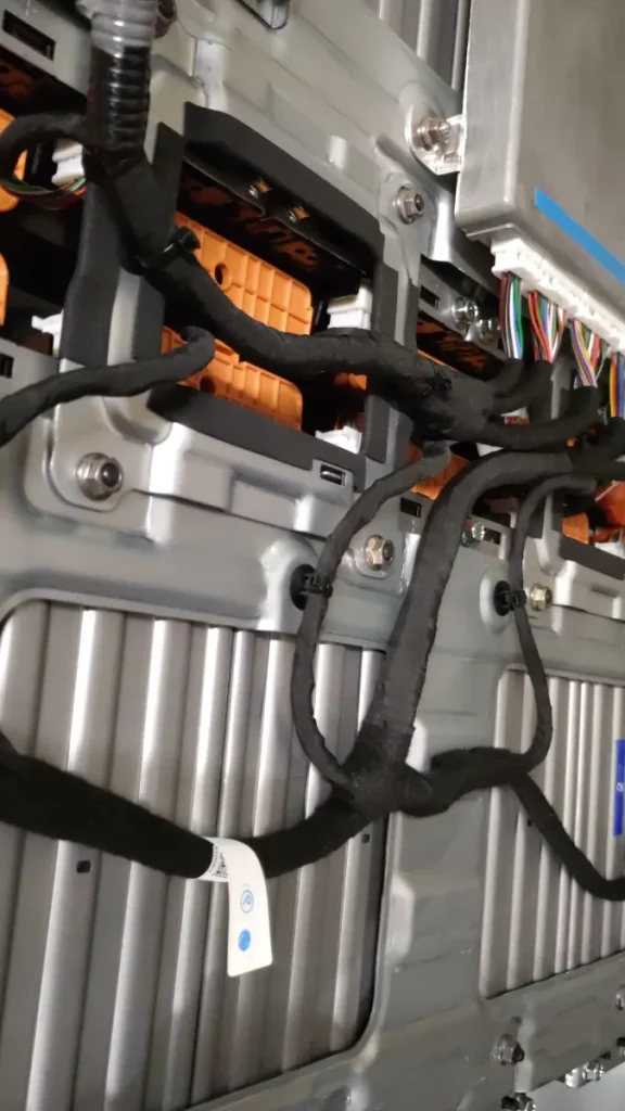
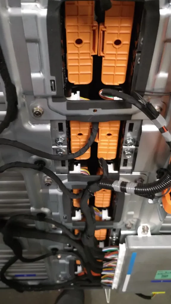
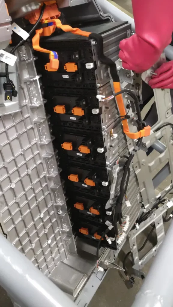
The individual modules are connected in series by busbars, which are enclosed in an orange plastic cover.
Next, we are going to work on the live battery in order to disconnect the modules. Please be aware that this is 400V DC, so we need to make sure that we use insulated tools in addition to the PPE.
By removing the busbars (second picture) we are breaking the pack and therefore reducing the voltage to a safe(r) level.

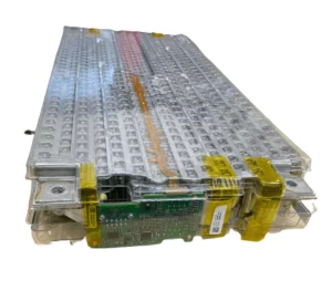
Here we can see the disconnected modules in the pack. The metal surfaces are the minus and plus connections of the modules, further right the white connector holds two thermistors for temperature control and the 8 voltage sensing connections for the individual cells to the BMS computer.

Here’s another view of the liberated and disconnected modules, still within the battery case:
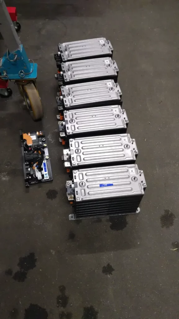
And here we have the first modules removed from the battery box:
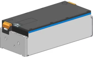
If we now go down to the single module, we can see the 8 individual cells, stacked on top of each other like chocolate bars (yes, I am Swiss 😉 !)
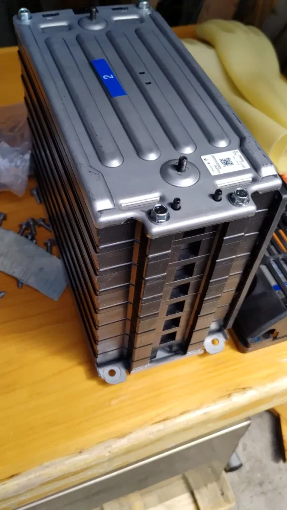
Each of these cells is made of 2 LG Chem (what I believe to be NCM 712) pouch cells, connected in parallel within the cell module. So in practice we have 16 pouch cells per module, the BMS of course only sees 8 cells.
So that’s the disassembly basically. I will now continue with some voltage measurements and the connectors pin arrangements in order to document these things here.
This battery will be going into the Renault Twingo, so stay tuned how this will work out!