Let’s have a closer look at the adapter plate on the gearbox side. It wasn’t easy to fabricate, and the most difficult part was actually to align the holes from the gearbox cover plate to the new adapter plate in a way that the central axis would still be perfectly aligned. It was eventually achieved with the help of a specifically fabricated caliper.
Before we went on with the fabrication of the plate itself, I printed the CAD drawing in scale 1:1 on paper and checked the alignment of the holes:

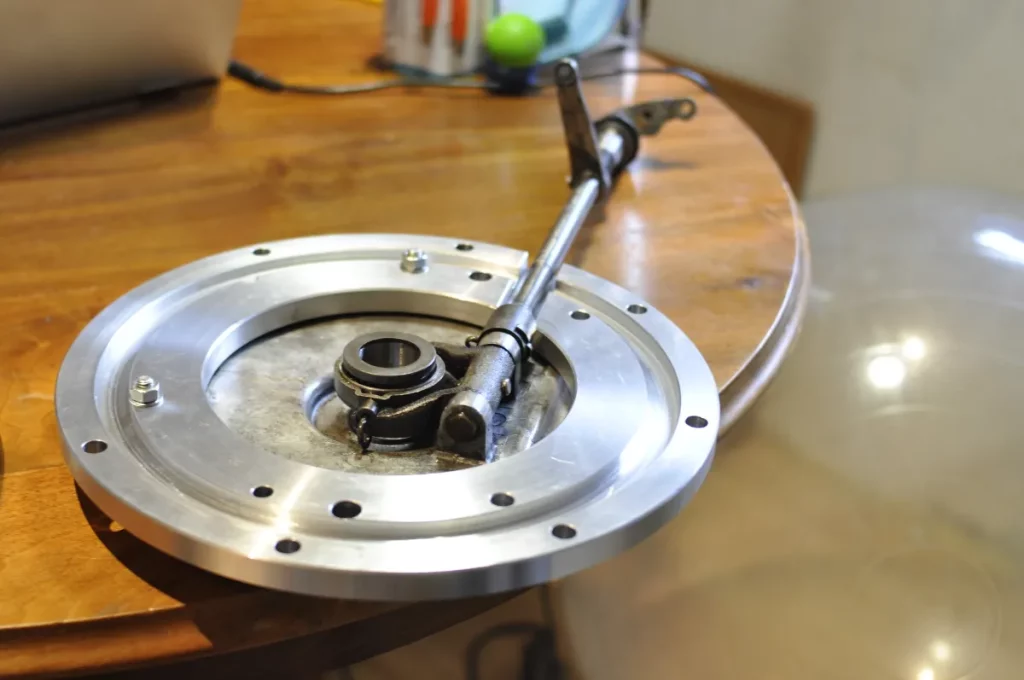
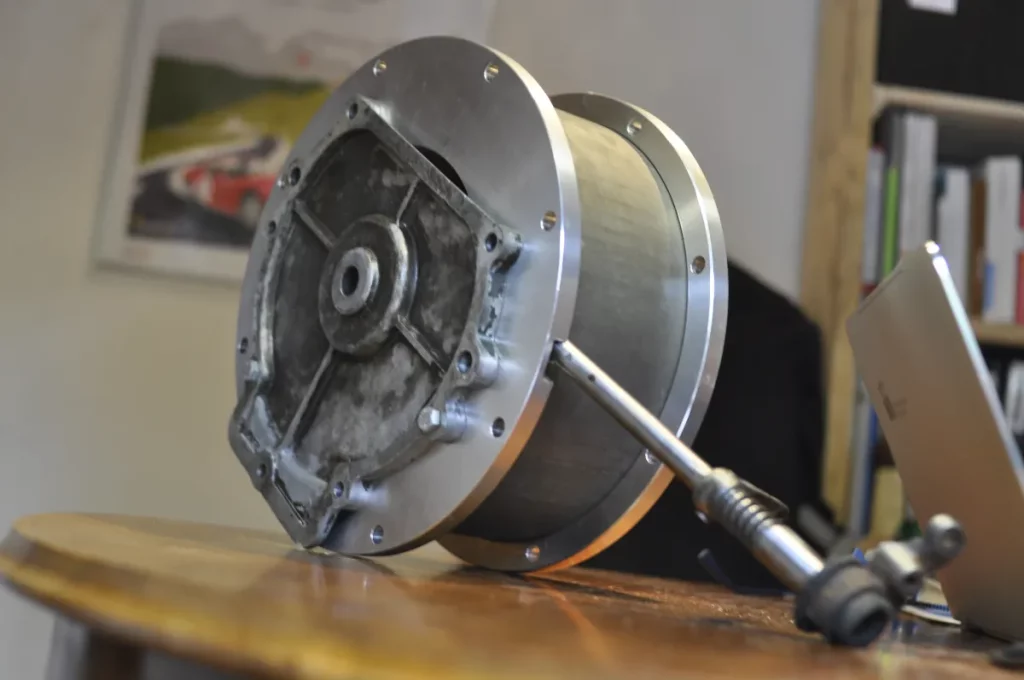
In the next picture you can see the gearbox adapter plate with the groove for the cylindrical cover that will serve as a clutch bell housing, the clutch control axis which translates the force applied to the clutch pedal to the release bearing (visible in the middle).
And just to see the whole assembly again with the new clutch bell housing:
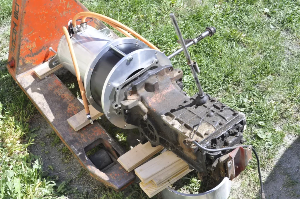
And here you can see the whole drivetrain consisting of motor, motor adapter plate, fabricated clutch bell housing and the gearbox (which in this picture is an old Renault 4 gearbox as you can probably easily identify by the gear lever sticking out on top of the box, as the real gearbox was already built into the car at that point).